Project
CAN Sensor Node
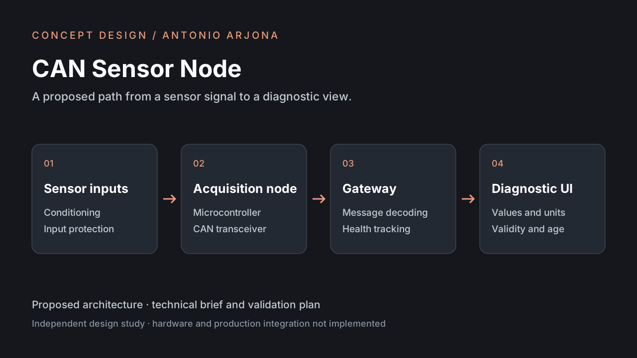
Design brief
How could a small sensor module make commissioning and fault diagnosis easier on a bench-scale machine? This original design study proposes a reusable acquisition node with clear channel status and a documented message format.
Current state: concept design. The deliverables are this technical brief, the architecture diagram and the validation plan. A PCB, firmware and hardware measurements have not yet been produced.
Proposed scope
- Four low-voltage analogue sensor channels on a protected bench supply.
- A microcontroller with a CAN interface and a separate transceiver.
- A configurable node identifier, a heartbeat and per-channel diagnostic status.
- A diagnostic screen showing raw readings, engineering units and stale data.
The concept is intended for a laboratory demonstrator. Electrical protection, component selection and PCB layout would need to be designed and reviewed before a hardware build.
Architecture and decisions
A sensor input would pass through conditioning and protection before conversion. Firmware would publish readings and health information over CAN. A separate gateway would translate the messages for a browser interface, keeping presentation concerns outside the acquisition node.
A fixed, versioned message definition would specify units, scaling, invalid values and update intervals. Separating sensor validity from the numeric value would help distinguish a real zero from a disconnected sensor.
Example data contract
An illustrative gateway record:
{
  "nodeId": 3,
  "channel": "temperature_1",
  "value": 24.5,
  "unit": "degC",
  "quality": "valid",
  "sequence": 128
}
This is a proposed software contract, not a recorded hardware measurement.
Validation plan
- Review the input range, protection strategy and proposed components.
- Exercise valid, out-of-range and disconnected-sensor conditions with a simulator.
- Check message decoding, sequence tracking and heartbeat loss.
- Build a bench prototype and compare readings with a reference instrument.
- Document results and limitations before considering a custom PCB.
Inspiration
Tal Zaitsev’s SENSE2CAN case study is a reference for documenting requirements, trade-offs and hardware debugging. This concept is an independent exercise; it is not a reproduction of that project or work performed for Tesla.